Constant current LED driver as a weapon of battery destruction

These Chinese fairy lights cost less than £5 somewhere on Amazon – you can get 3 for £8. In the ad there’s this lovely golden glow

but in practice the damn thing is dimmer than a Toc H lamp

not very bright – in design and in output

These things are basically a throwie upscaled to a 50 LED string. Powered by two CR2032 lithium cells in series, the LEDs are in parallel, Current is limited by the internal resistance of the batteries. The whole thing is a disposable hazard to the environment, intended for a single use at someone’s wedding or party. It shouldn’t be allowed 😉

They make quite a nice distributed light in an outdoor shed, where I can fix the wire along the ceiling, just as well as the solid enamelled wire is going to break if moved too many times. I was surprised that you could put 50 LEDs in parallel. They are all fed from one end, and in the original configuration you couldn’t see any gradation along the string. However, putting 700mA  through them generated a very welcome increase in light, and a slight gradation down the string, due to the voltage drop.I feared that would be bad for LED life, so I ran a third piece of enamelled wire through the string and fed one side of the LEDs from the far end and the other side from the near end, the drops along the string sort of cancel out. Using a light meter with the LED taped to it the original version as received gives a single LED output of 10EV, with 700mA it’s 15EV, a gratifying five stops more light – about 30 times more.

now a more healthy 15EV, typical of full sunlight on a cloudless day, although about 1mm from the LED

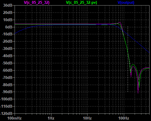
The 700mA is split among 50 LEDs, about 14mA per LED. I’ve never come across a LED (designed for illumination, rather than an indicator segment) that’s rated at < 20mA, so I figure I am OK.  I was looking to upgrade this to 12V, powering off three 18650 LiIon batteries. The obvious solution was a Chinese LED current limiting switchmode supply, but the obvious solution comes with a nasty wrinkle for battery powering. Current rushes up as the voltage drops

a constant current driver is a very unkind battery load

Run off 12V it worked a treat. I used three LiIon cells scrounged from laptop packs and bits, and I found that this is a weapon of battery destruction – first I wrecked two cells out of three, then another two. Hmm. On the upside, at least I have now selected the strongest cells. On the downside, four LiIon 18650s have met their demise.

What’s up? The constant current LED supply is one of these

5-35V 3W LED Driver 700mA PWM Dimming DC/DC Step-down Constant Current. From these guys on ebay

and I really should have been paying attention to that 5-35V spec, because as my Li-Ion’s fall from 11V down to 5V, it will say gimme, gimme, gimme more current, NOW.

Gimme all you got – particularly as the battery dies

And you don’t get to see that the batteries are running down from the LEDs dimming until it reaches less than 5V, because the driver is good for 5V. Oops. My bad. That’s why I am four 18650s down. Most things you run off batteries tend to draw less power as the voltage fades, but these suck the last dregs out of the battery in double-quick time, giving up just as it discharges the second weakest battery to below recovery.

I was imagining low-voltage disconnects and mucking around with P mosfets and PICs, then I spotted the PWM pin. You either leave this open, or ground the sucker to disable the output, the basic chip is the XL4001 from XLSemi. The EN wants to be < 0.8V to turn the thing off, and > 1.4V to turn it on. I had a vague recollection you could use a TL431 to get an active low power is high enough output, and Google delivered inspiration from ON1AAG on electro-tech online. TI also have a rather nice app note Using the TL431 for undervoltage and overvoltage protection which goes into some of the trials and tribulations of such misuse. One of which is quite a high Low condition voltage of about a volt or so – to wit

A lower bandgap reference voltage as seen in the TLV431, allows for a lower logic”low”output voltage without the need for external hardware.

Testing this with a LED showed it basically worked, but feeding the signal to the EN pin did ‘owt. As TI say, the resting Low voltage is over a volt. They’ve also got a Understanding Voltage References: Using a Shunt Reference as a Comparator blog series which points you at the TLV431 for this sort of thing. I needed to pad the output down with two diodes to get it just below 0.8V

Low Voltage disconnect for XL4001 PWM LED regulator

There’s no hysteresis in this. I did first consider a 5.6V Zener instead of the two diodes, but that introduces a nasty pathology. The LVD turns the chip off at about 10.5V, but switches it back on again at about 5V, and the XL4001 goes way-hey, let’s suck the maximum current out of these dead and dying batteries. At least with the diodes it has to get down to < 3V and the XL4001 doesn’t draw half an amp like it does at 5V since 3V is out of its operating region which is 4.5V to 40V.

I’d be better off with the TLV431, but TL431 is what I have to hand. I’ll get some TLV431 next time I order some parts.

Recycling Neato 4/5AA batteries.

Looking for an alternative I hit on an old Neato XV robot hoover battery up for recycling. These get thrashed in this application, but the problem is there are two 7.2V battery packs with six 4/5AA size NiMH. To me these look pretty much like 18650 size. One of the cells has gone high resistance, but the remainder charge well on my MAHA battery charger/analyser

A decent capacity of 3700 mAh, typical of all but one cell

Although no chemistry appreciates full discharge, NiMh will tolerate the odd deep discharge. I’ve learned my lesson running constant current LED drivers off LiIon batteries, and while I have a LVD now I’m not taking the risk again.

I’ve also got a chance of trickle charging these via a solar panel. Battery University say you shouldn’t trickle charge NiMH at > .05C which is ~180mA or less. Mine is an old Maplin 1.5W @17.5V solar panel which would theoretically give 86mA in blazing summer sunshine. Which is not the time of year when you want lights in a shed, so I’m not going to be anywhere near endangering these batteries 😉 11 of them will give me a nominal pack voltage of 13.2V


Piezo contact mics on low voltage power supplies

A few years ago I did a couple of piezo contact mic amplifier designs, because people often moan that these things sound tinny and crap. There’s a wrong way and a right way to use these – they want to work into a high impedance. Using Piezo Contact Mics Right sets you right. Trouble is these use a 9V battery, and it seems world + dog want to use 5V, because that’s what they had. Time was when power supplies were +/- 15V for analogue and 5V for digital, but that’s a different story for later.

So what can you do with your piezo contact mic at 5V then?

Not much. If you are looking for low signal level performance an emitter follower biased at an output of 2V would work well, but if you only have 5V available it’s likely you are trying to digitise this signal and bung it in an Arduino or something. In that case, think laterally. Toss the power supply. I developed those amps because as a field recordist I wanted to hear faint signals from the contact mic. You know, like the whispering in the rails as a distant train approaches, though you need to avoid the Fredzania Thompson ending.

These days people would look at you funny if you attach a box with wires to the underneath of the rails. Don’t try this at home and all that.

Turns out many people want to use their contact mics on an instrument, or drum pad, or generally something they bash seven bells out of. Life is a lot easier for you. As established in Using Contact mics right, you want an input resistance of about 330kΩ so the bass doesn’t roll off with the typical series tens of nF capacitance of the sensor. 330kΩ is a damn sight more than your typical plug-in-power audio recording doohickey, which usually feeds the electret mic power from 3V via about 6.8kΩ. I measured my Olympus LS-14 and even the line input is 10k.

So stick the 330kΩ resistor in series with the input. Even writing that makes me cringe, because it will lose a hell of a lot of signal level, making a potential divider with the input resistance – for a 6k8 input you’ll take a loss of 33dB. That translates into a direct worsening of your noise figure by that much, that’s a lot of performance to throw away1. OTOH it works perfectly well down to 1.8V, it’ll be OK down to 0V as it doesn’t use power 😉

how much signal do you get from a piezo contact mic?

Let’s take a look at the sort of signal level you get from a piezo disc sensor. I got one on the bench and fed it into a DrDAQ signal capture device and Picoscope Continue reading “Piezo contact mics on low voltage power supplies”

Raspberry Pi 4 with touchscreen and FLdigi

I got a new Raspberry Pi v4 and the official touchscreen. The aim of this is to be able to run FLdigi and WSJT-X1 in a portable setup. Also to stop FLdigi getting hopelessly confused on my main PC – with two sound cards already adding a third sound card as interface for the radio meant portaudio, whatever that is, gets hopelessly confused on Windows and loses touch with the hardware intermittently.

Setting it up was surprisingly painless – blow a new 16Gb SD card with Raspbian, connect screen to the 5V and 0V on the GPIO and the ribbon cable to DSI. Normally you then have to remember to add the empty file ssh to the boot partition with the PC so you can talk to the damn thing, and perhaps wrangle the wireless config if the Pi doesn’t have Ethernet.

With the touchscreen I didn’t need all that. Although I started it up on ethernet, the onboard Bluetooth meant I could connect a Bluetooth keyboard using just the touchscreen, and then set up the wifi in the usual way. The touchscreen needs a reasonably firm press, this is no responsive smartphone screen, and being so small it is sometimes hard to get the right target, even with a conductive stylus, particularly as I set the font size a little smaller to use the screen area more. Continue reading “Raspberry Pi 4 with touchscreen and FLdigi”

International Dawn Chorus Day – getting bird sounds indoors without opening the window

International Dawn Chorus Day 2020 is somewhat overshadowed by the coronavirus pandemic for its human listeners. The birds probably appreciate getting some peace! The Wildlife Sound Recording Society was after getting a live broadcast of this from as many members as possible. They proposed two methods of live broadcast, their preferred option using Mixlr and a more gonzo alternative using locusonus.

Mixlr seems all about tablets and mobile phones. If a project’s got a mobile phone in it I’m not interested. I loathe smartphones – jack of all trades and master of none. They don’t do stereo1, FFS… Mixlr is Cloud. I don’t do Cloud, particularly if it comes with a subscription. It’s bad  enough when Cloud goes AWOL and you’ve put effort into the platform for free. Pay for the privilege?  Nope.

So I passed on that and went to locusonus, who are doing this under the Reveil soundcamp moniker. Locusonus is funded by the French State, bless their arty dirigisme – just look at their publications. And sponsors

So arty! So French!

Reminds me of reading about musique concrete as a kid in the 1970s, IRCAM and all that, while I was piddling about with a hand-me-down Stellavox tape recorder. Mad, but inspirational. I’ll hitch a ride on French exceptionalism.

I’m lucky in that way back when I bought a Cirrus Logic sound card for a Raspberry Pi. Or perhaps unlucky in another way – I never found a good use for it till now, as the software drivers were a whole load of hurt. By the time they got incorporated into Raspbian, the card was end-of-lifed so you can’t buy them any more.  That’s Linux for you. Free as in beer but slow to integrate hardware. If you are doing this from scratch, either use a cheap audio adapter with mono audio or something like the Behringer UCA202 USB audio card – stereo line in and works great with the Pi, right out of the box.

Despite fiddling with the CirrusLogic on and off I came to the conclusion a timed bird sound recorder is better done with a Dribox and a real audio recorder and a timer. However, a Pi and the CL card is perfect for locusonus. Perfect enough, indeed, that downloading the relevant Pi SD card image, blowing it onto a SD card and firing it up on ethernet gave me an instant win2, using a set of OKMII binaural mics into the line in port with the bias enabled.  I was able to hear myself, albeit at a low level, but the locusonus software lets you ram the Cirrus programmable gain amp up to +30dB and max digital gain. Sure, it’s noisy, but showed the principle.

Now all I need is an outdoor microphone Continue reading “International Dawn Chorus Day – getting bird sounds indoors without opening the window”

Fixing a short-sighted Logitech C920 HD webcam.

The Logitech C920 is a lovely little webcam, and having the MP4 conversion on the onboard processor means you can use it with gutless hardware. I got mine as a cast-off from Jason at Wildlife Gadgetman and wanted to use it for video-conferencing, what with the coronavirus lockdown and all that.

Trouble is the damn thing is short-sighted. It seems to be a common problem with the C920, and the autofocus is ratty. Sometimes it would work, sometimes not.

I am short-sighted too, so a temporary fix to get it to focus on distant objects is to Sellotape one lens my glasses over the front, but it’s not a good look. AF was still ratty. Poor distant focus is a common complaint with the C920. This fellow shows you how to take it to bits

but unlike him, my fault was the little piece of metal had become loose and was fouling the movement of the lens.

the squarish metal washer with three notches had come adrift.

Extracting the washer from the lens, using the notches to pass the castellations on the lens mount let me isolate it

I did consider leaving it off

but figured I’d get flare from reflections from the plastic cover in front so I used thick superglue, carefully to avoid getting it on the lens. Four dabs at the corners sorted it.

Job done, sorted. This doesn’t seem the only way for these cameras to misbehave on focus, and unfortunately you can’t see the errant washer because of the baffle  on the plastic cover. But you have to take it to bits if your problem is the focus is off as the one in the video. There’s a neater way to do the glasses thing with an eyepiece adapter lens as in this video, which doesn’t entail taking it to pieces, but that wasn’t the problem for me.


Maplin geiger counter

Maplin published a design for a Geiger counter a year after the Chernobyl explosion in the September 1987 issue of the Maplin Magazine. I bought the kit for the remote head and constructed this. I never built their meter, because I used two CD4017 decade counters to make a faux dekatron display, feeding the output of the chain into a mechanical counter bought from H.L. Smith in Edgware Road in the early 1980s. Edgware road used to be a haven of weird and wonderful surplus electronics shops.

I’m not really sure why Maplin didn’t go the counter way, it’s not like seven-segment LED displays didn’t exist then. The dekatron display is better than a digital count for the first couple of digits, because the spin of the display gives a feeling of count rate, in a way that changing digital display numbers doesn’t.

Counter part of Geiger counter

The kit was shockingly expensive at the time – the Maplin Magazine shows the kit was £79.95 in 1987. That’s about £221 nowadays. Perhaps markups were much better in Maplin’s geeky heydays, whereas now they are competing against Banggood and Dealextreme. The original schematic shows an oddball AG1407 GM tube, it looks like I couldn’t afford the kit when it came out and built it in the early 1990s, when they had substituted the LND 712 tube, which is still made, LND 712 datasheet here. Datasheet seems to indicate 6E-5 R/hr for a count rate of 1CPS for Co60 source, so a conversion 0.0036R/hr for 1CPM

Continue reading “Maplin geiger counter”

Olympus LS-14 clock fix

When I bought an Olympus remote control to reverse-engineer the Olympus remote control code, I got a Olympus LS-14 for £30. I’ve had a LS-10 for donkey’s years, these are reliable. However, the RS-30 is £60 and there was a LS-14 with RS-30 on ebay for £90. The LS-14 is a nice machine, key things that it does better than the LS-10 are a pre-roll buffer and the sound is a little bit more natural from the mics, where the LS-10 could venture on the tinny side.

It can also sample the first 12 seconds of sound to set recording level, should you lack the smarts to be able to learn how to set record level yourself 😉 No automatic recording level setting has ever been made that works properly, although the smart recording feature will work fine for a band running a sound check in the first 12 seconds, it leaves record level alone after the initial sound check. The feature is about as useful as a chocolate teapot on unscripted field recordings and wildlife

The clock on my LS-14 wouldn’t keep time. Indeed, after a couple of days I’d turn it on and it would invite me to set date and time. That’s easy enough to do, but irksome to do regularly, and usually means the lithium clock backup battery is shot.

Manufacturers do clock backup in various ways – some use a lithium primary cell, on the principle that planned obsolescence means you should have changed the device out in three years. You throw it away and buy a new one. Others use a supercapacitor, charged from when the device is switched on. That works well, these have a service life of about 10 years, you can buy replacements on ebay. Some use a rechargeable lithium cell, again these have a ten-year plus lifetime.

Nobody else seems to moan about the clock needing resetting on the LS14, so Google was not my friend in this case. I suspect mine had been in storage for a while. There was something about the seller getting this for his daughter to use at uni and it didn’t work out. Perhaps he left it in the garage or a shed in the damp. There’s not much else made of mild steel in the LS-14 to compare.

Dismantling the LS-14.

Take the three screws out the back. You do not need to remove the screws on the microphone housing. To get at the battery sadly you will need to take out the little board at the very back. It has a plug on connection to the main board, use your intelligence and ease this off. I had to unsolder one of the main battery connections. You will be presented with the main board, and the offending article can be seen here.

You can see that the battery is rusty as hell. Couldn’t decide whether the chemical splurge was the flux from the solder or some battery catastrophe. It was stiff like flux, whereas battery ooze usually wipes off.

The battery looks like bad news, particularly as I have not managed to determine the type or a replacement number. Probing with a multimeter showed it is charged to about 3V when the unit is powered.

battery close-up

Since I didn’t know what sort of part this was – rechargeable battery of supercap, I had a go at it with a fibreglass pencil to clean off the rust. I’ve had this experience with watch batteries – if you have one leak in a watch you have got to get all of the gunk out of the battery compartment, else you will find replacement watch batteries only last a few months before dying. That means either a special type of watchmaker’s putty, which is the right way to do the job, or q-tips and isopropyl alcohol. This is a less critical case than a watch. I don’t mind resetting the clock after a few months of non-use, it is resetting it after less than a week that hacks me off. I figured all that rust was possibly giving a high-resistance leak across the battery shortening battery life.

Luckily for me, cleaning all the rust off this was a win, the clock keeps good time and lasts over a couple of weeks still ready to be used again. So if you have trouble with the clock needing resetting in your Olympus LS-14, give cleaning the battery a go. I needed a replacement for my trusty LS10 which has been claimed by another family member, so fixing this means I have a useful upgrade now.

Maplin once supplied geeks with geiger counters and laser tubes rather than overpriced Chinese tat

Back-from-the-dead supplier of marked-up Chinese tat Maplin started life out as a supplier run by geeks for geeks, with a wide range of electronic music modules and later on projects which didn’t have any real use, but were technical curiosities.

Maplin sold a lot of Geiger counter kits in the years after Chernobyl. Mine is still in service, I vaguely seem to recall the tube was a ZP1401 with the thin mica window. It saved me a radon survey –radiation is a problem in the south-west with radon leaching out of granite underground. The Geiger counter reads lower in the basement than on the first floor my old house (Maplin’s tube was a mica-window type). Interestingly in 1996 Maplin magazine claimed that the prototype of this detected the Chernobyl cloud passing over Britain.

Another story behind the scenes was that during the testing phase of the Geiger Counter project, the normal background radiation readings rose significantly, these were recorded for prosperity on a printout.We later learned of Chernobyl, the world’s first major nuclear accident. It was detected here first at Maplin [^1]. The implication of this is that the radiation cloud passed over Britain, and not just contaminating the hillsides in Wales.

The display is styled after the dekatron counter tubes in my school’s Griffin and George Physics lab Geiger counter
Continue reading “Maplin once supplied geeks with geiger counters and laser tubes rather than overpriced Chinese tat”

In rural Wales you still need an AM radio, until the last tube fails in service at Droitwich

We used to match the medium to the message and the terrain, but now we seem to assume mobile data is everywhere. AM radio is dying, because everybody is online. Except when they aren’t.

Bwlch Y Groes

I recently went hillwalking in Wales, and it’s handy to have the weather forecast, and FM doesn’t really happen in remote Wales. I was lucky enough to still have Radio 4 Longwave reception on 198kHz, but I was surprised at how quickly FM became useless in Wales. RDS doesn’t really help because the problem is there is no alternative signal to switch to in a lot of Snowdonia. There’s no useful mobile signal in a lot of mid-Wales either – I have a dual-SIM dumb mobile (which ahs better RF performance than a smartphone), on the O2 and Virgin networks for diversity of networks, and that doesn’t get anything in large parts of the hills.

Continue reading “In rural Wales you still need an AM radio, until the last tube fails in service at Droitwich”

Improved OpenEEG filter design

The original OpenEEG filter design had a poor performance that made me reluctant to construct that project, although the price was right. I had proposed a replacement elliptical filter

the magenta line is the theoretical version, the green using preferred values. The blue line is the original OpenEEG one

using this design

This schematic is duplicated, one for calculated and one for preferred values

which turns into this

no great prizes for neatness…

I had the devil’s own job trying to measure this, trying to avoid plotting it out by hand the old way, although that would be the right way 😉

Running a Wien bridge oscillator through it showed me I had one  null, which was rough, because I’d ordered two 😉 one was at 148Hz, and another very very faint one at 534Hz, which was wrong, it should be at 272Hz. Scoping the output of the first section showed that was the culprit, I had put in 1.8k as R23 instead of 6.8k. My nulls are now clear and in the right place. I try sweeping the filter using Rightmark audio analyser. First it moans it can’t find the 1kHz sync tone, well, yeah, I don’t really expect to find that at the output of this filter. Running stereo with left straight through finds the sync, but Rightmark sells this to young pups setting up their car stereos presumably, so they want you to pay for having any useful low-frequency resolution, and I’m not prepared to pay.

I tried running white noise through the filter and FFTing the result. Connecting it to a USB Behringer UCA202 gives me hum from a ground loop through the scope and computer, so I recorded the output using a handheld battery audio recorder to get rid of that. The sound is really quite strange

FFT of the filter response. Sweeping the filter manually shows both nulls are deeper in practice. Click to see the original fiel where the thin trace gets to show better

Unfortunately the FFT has no real resolution of the dips, the second is lost in the mush although it can be seen when manually sweeping the filter. Still, how did I do given the real filter is better than the FFT sweep? Say the passband is about -28dBFS, at 128Hz I am about -66dBFS, about 38dB down. OpenEEG were at about -16dB there, so I have roughly doubled their performance. Trash at fs/2 + x tends to alias to fs/2 -x, ie the HF end of the passband, 64Hz.  The highest of the Mind mirror filters was at 38Hz, so I am interested in the attenuation at say 128Hz + (128-40) = 216Hz, since rubbish up here will fold down to the MM high frequency filter. That’s about -80dB, so I am about 52dB down by then, again about twice OpenEEG’s -24dB. It’s not quite the -60dB which would dump a full-scale signal at 216Hz into the 10-bit quantisation noise, but it’s close.

What this filter won’t do is help you against mains hum for 50Hz. It starts to roll off starting about 70Hz, so that hum will go right through regardless. It is also not a candidate for massive miniaturisation, those caps are big. Sure, it can be built tighter on a PCB, but it won’t ever be tiny. No point in buying the Olimex box for the OpenEEG product if I go that way, and no point running the SMD version.

I figure this is a creditable improvement on the openEEG filter, almost worth manually plotting out the frequency response to see what it is uncluttered by FFT artifacts

Swapping to lower-spec parts

I constructed this with a NE5532 run off +/-12V, because I wanted to see it running right. The next stage is to try a LM358, I am not sure such a nasty device will have the performance for an elliptical filter, which needs a high Q for the nulls. But it is a very low-frequency filter, so I may still have enough gain/bandwidth product. I can pull the 5532 and see if the nulls shift or soften. It’s tough that OpenEEG has only a +5V rail. That’s within spec for the LM358, but the output will only swing from 0V to 3.5V, arguably I should bias these mid-rail to 1.8V rather than 2.5V . Ideally I want a quad rail to rail 5V opamp, something like TI’s LMC660C.