The original OpenEEG filter design had a poor performance that made me reluctant to construct that project, although the price was right. I had proposed a replacement elliptical filter
using this design

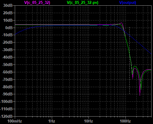
which turns into this

I had the devil’s own job trying to measure this, trying to avoid plotting it out by hand the old way, although that would be the right way 😉
Running a Wien bridge oscillator through it showed me I had one null, which was rough, because I’d ordered two 😉 one was at 148Hz, and another very very faint one at 534Hz, which was wrong, it should be at 272Hz. Scoping the output of the first section showed that was the culprit, I had put in 1.8k as R23 instead of 6.8k. My nulls are now clear and in the right place. I try sweeping the filter using Rightmark audio analyser. First it moans it can’t find the 1kHz sync tone, well, yeah, I don’t really expect to find that at the output of this filter. Running stereo with left straight through finds the sync, but Rightmark sells this to young pups setting up their car stereos presumably, so they want you to pay for having any useful low-frequency resolution, and I’m not prepared to pay.
I tried running white noise through the filter and FFTing the result. Connecting it to a USB Behringer UCA202 gives me hum from a ground loop through the scope and computer, so I recorded the output using a handheld battery audio recorder to get rid of that. The sound is really quite strange

Unfortunately the FFT has no real resolution of the dips, the second is lost in the mush although it can be seen when manually sweeping the filter. Still, how did I do given the real filter is better than the FFT sweep? Say the passband is about -28dBFS, at 128Hz I am about -66dBFS, about 38dB down. OpenEEG were at about -16dB there, so I have roughly doubled their performance. Trash at fs/2 + x tends to alias to fs/2 -x, ie the HF end of the passband, 64Hz. The highest of the Mind mirror filters was at 38Hz, so I am interested in the attenuation at say 128Hz + (128-40) = 216Hz, since rubbish up here will fold down to the MM high frequency filter. That’s about -80dB, so I am about 52dB down by then, again about twice OpenEEG’s -24dB. It’s not quite the -60dB which would dump a full-scale signal at 216Hz into the 10-bit quantisation noise, but it’s close.
What this filter won’t do is help you against mains hum for 50Hz. It starts to roll off starting about 70Hz, so that hum will go right through regardless. It is also not a candidate for massive miniaturisation, those caps are big. Sure, it can be built tighter on a PCB, but it won’t ever be tiny. No point in buying the Olimex box for the OpenEEG product if I go that way, and no point running the SMD version.
I figure this is a creditable improvement on the openEEG filter, almost worth manually plotting out the frequency response to see what it is uncluttered by FFT artifacts
Swapping to lower-spec parts
I constructed this with a NE5532 run off +/-12V, because I wanted to see it running right. The next stage is to try a LM358, I am not sure such a nasty device will have the performance for an elliptical filter, which needs a high Q for the nulls. But it is a very low-frequency filter, so I may still have enough gain/bandwidth product. I can pull the 5532 and see if the nulls shift or soften. It’s tough that OpenEEG has only a +5V rail. That’s within spec for the LM358, but the output will only swing from 0V to 3.5V, arguably I should bias these mid-rail to 1.8V rather than 2.5V . Ideally I want a quad rail to rail 5V opamp, something like TI’s LMC660C.