Plug-in-power
Electret microphones only need the power for the FET buffer stage, as the capacitor diaphragm polarising voltage is built in at manufacture.
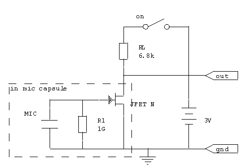
Fig.1 Battery powered electret microphone schematic (part values may vary)
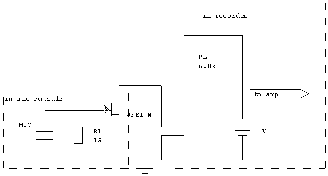
The circuit diagram of a typical electret microphone is shown in Fig.1 - in practice a DC blocking capacitor would be added at the output but we will imagine this forms part of the recorder input for the moment.With a small modification, the battery and load resistor can be taken inside the recorder, eliminating the need for the switch but still retaining the two-wire unbalanced connection path, as shown in Fig.2
So far so good. Unfortunately the load resistor RL and indeed the operating voltage vary between different recorders. Unlike 48V phantom powering there is no defined standard way of doing this, so the mic operating conditions are in an unspecified condition. HiMD recorders such as the Sony MZ-NH700 have the supply in this schematic[1] running at a meagre 2.3V. Thus even if the capsule tolerated a mere 0.5V across it the current available would only be 0.27 mA and the absolute maximum is 0.33mA (substantiated by short-circuit current measurement). There are some PIP mics this HiMD will not work with correctly because of this. My old Kenwood DMC-F5R used a voltage of 5V to supply the PiP and did not have problems powering any PIP mic I had.
DIY constructors should also beware. The popular Panasonic WM-61A capsule is specified at 2V operation[2], and loses 3dB of sensitivity at 1.5V. It requires 0.5mA, and drawing 0.5mA form the MZNH700 is just not possible. The capsule will run out of spec and starved of current. A better way to use this capsule is to use a battery box, along the lines of Fig.3
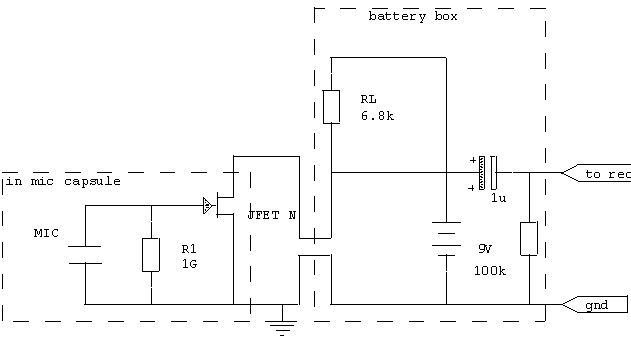
Fig.3 Battery box with
plug-in-power mic.
You don't need a switch for the battery if you remember to unplug the PIP mic when it is not being used. Purists may want to put a capacitor across the battery, and wildife sound recordists may want to reduce the value of the 1u output capacitor to 0.1uF which will form a 200Hz rolloff working into the assumed 6.8kΩ load of the following recorder PIP input. A battery voltage of 6-9V will still achieve at least 2V across the capsule at 0.5mA.
back to mic powering