I have some time to do more recording now. Okay, so it’s not hyper-original recording trains but I liked the screech of the wheel flanges as it rounds a fairly gentle bend. I was at the same level as the track across a dip due to the lie of the land
Also a chance to see how this Audioboo thing works… which seems to be pretty well 2018 update – they decided to start charging $9.99 a month. You must be kidding, guys, I may as well pay WordPress £33 a year to be able to get audio facility. There’s no low-end offering.
The 16F628 pic doesn’t actually have a A/D converter. It has a couple of comparators and a software controllable voltage reference which does pretty well for most applications. I’m looking at using it for a low-battery cutoff device to protect 12V lead-acid batteries.The two comparators would work for that – one for the low-water mark, and one set a little bit above for a level the charge needs to reach before the load is reapplied, with some time delay probably too.
However, I came across Microchip’s Application note AN700 Make a Delta-Sigma Converter Using a Microcontroller’s Analog Comparator Module which shows how to use the comparator as an A/D converter. There are plenty of PICs that already have an A/D converter – the 16F88 has several analogue channels, but the 16F628 is cheaper. A lot of applications need just one analogue value sampled, and my application also wants an A/D that includes 12V. If I used a chip with an onboard A/D I’m going to need two resistors anyway to pad 12V down to the 5V range, and AN700 fig 7 shows how to take advantage of the external parts to shift the A/D range up to about 12V.
Trouble is, I want to use JAL, to make life easier when I write the rest of the code, and the assembler mode of JAL didn’t work. I swiped this from here probably derived from here but it didn’t work for me. I took a look at the code and suspected the assembler part, because what was happening was as soon as I called the DeltaSigA2D() the whole program seemed to sit down and start again from the top, resulting in endless printing of “STARTED” and little else.
Thinking about what JAL is probably doing with assembler, I suspected some of the clever space-saving constructs like the bit in eat5cycles that goes
goto +1
which was supposed to be
goto $+1
could be asking for trouble unless I could really assume that next instruction is the next one in the program space. In the end if you’re going to use something like JAL you aren’t trying to eke out every last drop of code space, so I figured I would nut the cleverness and use stacked nops. And it worked.
-- JAL 2.4i
-- Just the A/D 15 June 2013
-- modded by Richard
--
-- adc_test_16f628_v03
-- after DeltaSig.asm v1.00 from Dan Butler, Microchip Technology Inc. 02 December 1998
-- after http://den-nekonoko.blog.so-net.ne.jp/2010-11-25 and AN700
-- continually spews 10-bit value on TXD at 9600 baud, 5V=1024 0V=0
-- AN700 Fig 2
include 16f628_inc_all
-- We'll use internal oscillator. It work @ 4MHz
pragma target clock       4_000_000
const word _fuses         = 0x3fff ; default value
pragma target osc         INTRC_NOCLKOUT
pragma target WDT    off
pragma target MCLRE  off
pragma target PWRTE  on
pragma target BODEN    on
pragma target LVP    off
-- HS, -BOD, ,-LVP, -WDT, -CP  = 0x3F22
; pragma target fuses       0x3D02
--enable_digital_io()

; const bit enhanced_flash_eeprom = false
include pic_general
include delay

var word result
var byte result_l
var byte result_h
var byte counter1
var byte counter2

const byte booted[] = "STARTED"

pin_a0_direction = input
pin_a1_direction = input
pin_a2_direction = input ; comparator in / vref out
pin_a3_direction = output ; comp1 out
pin_a4_direction = output ; comp2 out (OD)
pin_b2_direction=output ; RS232 TX

const bit usart_hw_serial = TRUE
const serial_hw_baudrate = 9600
include serial_hardware
serial_hw_init()

include print
include format

Procedure InitDeltaSigA2D() is
VRCON=0b11101100 --    0xEC
CMCON=0b00000110   -- 0x06 two common ref comps with outputs
end procedure

;
; Delta Sigma A2D
; The below contains a lot of nops and goto next instruction. These
; are necessary to ensure each pass through the Elop1 takes the same
; amount of , no the path through the code.
;
Procedure DeltaSigA2D() is
assembler
         LOCAL    elop1,comphigh,complow,eat2cycles,endelop1,eat5cycles,exit1
--DeltaSigA2D
        clrf counter1
        clrf counter2
        clrf result_l
        clrf result_h
        movlw 0x03 ; set up for 2 analog comparators with common reference
        movwf cmcon
elop1:
        btfsc c1out ; is comparator high or low?
--        btfsc cmcon,c1out ; is comparator high or low?
        goto complow ; go the low route
comphigh:
        nop ; necessary to timing even
        bcf porta,3 ; porta.3 = 0
        incfsz result_l,f ; bump counter
        goto eat2cycles ;
        incf result_h,f ;
        goto endelop1 ;
complow:
        bsf porta,3 ; comparator is low
        nop ; necessary to keep timing even
        goto eat2cycles ; same here
eat2cycles:
        goto endelop1 ; eat 2 more cycles
endelop1:
        incfsz counter1,f ; count this lap through the elop1.
        goto eat5cycles ;
        incf counter2,f ;
        movf counter2,w ;
        andlw 0x04 ; are we done? (we're done when bit2 of
--        btfsc status,_z ; the high order byte overflows to 1).
        btfsc Z --status,z ; the high order byte overflows to 1).
        goto elop1 ;
        goto exit1
eat5cycles:
        nop  -- this really seems to hate the goto $+1, keeps resetting. I am not so short of code space, case to be made to turn everything into nops
        nop
        --goto +1 ; more wasted time to keep the elop1s even
        nop ;
        goto elop1 ;
exit1:
        movlw 0x06 ; set up for 2 analog comparators with common reference
        movwf cmcon
end assembler
end procedure

function rescale(WORD IN value) RETURN WORD is
-- 1024 corresponds to 5V
-- multiply by 50000/1024 (~49)
var word temp =value*49
temp=temp/100 -- now lose excess precision
return temp

end function

InitDeltaSigA2D()

print_string(serial_hw_data,booted)

forever loop
DeltaSigA2D()
result=word(result_h)*256 + word(result_l) -- you must explicity make result_h a word as described on p11 of JAL manual
result=rescale(result)
format_word_dec(serial_hw_data, result, 3, 2)
serial_hw_data = " "
serial_hw_data = 13 -- CR
serial_hw_data = 10 -- LF
delay_1ms(500)   -- this is purely to allow the terminal display to catch up and not overload buffer of the slow device
end loop
There’s a case to be made for using a voltage reference and setting it to be some convenient power of 2 like 2.05 V to save all the messy integer calculation in rescale
This is a video of the display on the serial port compared with a multimeter on the input, connected to a 5k pot between 0V and +5V. I should have moved the control a bit slower to allow the 0.5s sampling to catch up at times, but it shows it is reasonably accurate.
The trouble with geese is that they are waterfowl, ie used to hatching near water, unlike chickens, so you tend to have to control the humidity of the incubator as well as the temperature. Humidity is terribly counterintuitive – unlike temperature humans have no real sense for it. So I was looking at how to make a humidity and temperature sensor.
Goslings. Like most animals, geese don’t look so mean when young
The problem starts with our cheap Chinese import incubator. There’s no real calibration on the temperature dial, and you know it’s a bad sign when the manual tells you ‘when your small poultry is ready’. I was really sceptical about how well this would stabilise the temperature. Quite unfairly as it happens. Continue reading “Humidity and Temperature sensor on Cosm IoT”
I bought this preamplifier secondhand from Subjective Audio in 1984. My amplifer is a Mark 1, by the way, other models may be different.It has provided me with thirty years of listening pleasure, a good investment by my younger self. However, it is getting elderly and the volume control got scratchy. I shut it down for a few months while I mulled over my options. Remember this is a product that can ship out a signal of 60V, you don’t want a scratchy pot getting worse and sending 10V peaks into a power amp designed for 0.775Vrms full scale. You just don’t wanna go there…
This one can bite
Before you even think of reading further, note that opening the lid of this amplifer could easily kill you, not only is it mains powered but the rectified HT line operates at 630VDC. A high voltage DC shock is a totally different experience to a mains shock. If you have survived a mains shock you won’t necessarily survive a DC shock 😉 you have been warned. Here is ARC’s take on the matter:
Technical servicing of Audio Research vacuum-tube models should only be done by a trained audio electronic technician. Operating voltages inside these products can be lethal, and owners are advised against any tampering with internal components. Unauthorized modifications or circuit changes to Audio Research products immediately voids any protection under the terms of the 3-Year Limited Warranty.
I’m not just any old owner of an SP8. I learned electronics as a teenager in less litigious and more enterprising times picking junked tubed TVs out of skips and scavenging parts. Later on I worked as a broadcast engineer years ago and worked with high voltage TV cameras and monitors, before moving on into electronics design. If you have only worked on low voltage electronics then beware. Old stagers tended to work with one hand in their pocket because an electric shock across the chest is particularly bad for your health.
You have been warned. If you have any doubts then don’t do this. It is a lot easier to buy a new preamplifier than to buy a new life.
Now one option would be to return this to ARC in Minnesota, however, a glance at the T’s and C’s of their servicing indicates this isn’t likely to be a cheap option. The secondhand cost of an SP8 is about £650 these days, which sets the limiting case of what it’s worth to spend on one.
How to change the Audio Research SP8 volume control
The nice thing about this is that you can do this job from the top. Remove the screws holding the top lid, and save them carefully. They are some curious coarse American Imperial thread, fortunately the same as the sort that come on many PCs if you lose some.
First familiarise yourself with the patient. The circuit diagram is here,
Audio Research SP8 preamplifier circuit diagram (schematic)
You’ll observe a thin circuit board at the front, right on top. Your mission is to replace the volume control which is on the left hand side. First unplug the line stage valves, remember which are which. Indeed, get a digital camera and photograph where everything is before you dismantle it. Then unsolder the three wires that go to the line stage from the top control board.
unsolder these three wires to be able to lift the control board to replace the volume control of the Audio research SP8
These have stiff wire wound round the end, poked through a hole in the PCB. You can heat up the pad and lift from the top. I only realised life gets easier if you remove these after I had unsoldered the pot. It’s easier to unsolder these first, then remove the pot.
Remove the four knobs with an Allen key. remember being American, the ARC is gloriously unreconstructed imperial feet and inches, none of that cheese-eating surrender monkey metric hoo-hah here, so use an imperial Allen key set. Set the knobs aside, marvelling in their honest-to-God solid metal construction. Observe that there seem to be two diameters of shafts here, the pot shafts on volumegain and balance are slightly thinner than the switch shafts on source select and that odd mono/stereo/left/right thing which I’ve only ever seen on ARC gear.
Next get yourself a ½inch AF socket, or if you are careful, a ½” AF ring spanner, and unscrew the nuts holding the pots and two switches, plus the associated star washers. Set to one side. All the threads seemed to be the same despite the different shaft diameters.
Now very carefully move the board back and lift the volume control end. Remember that your amplifier, like mine, is likely to be very elderly, and being vacuum tube gear will have been thermally cycled zillions of times. That means the wires and plastic will be stiff and perhaps brittle. The last SP8 was produced in 1985. That means at least thirty years will have passed. Go easy on the old girl, right 😉
A solder sucker and a 25W or more temperature controlled soldering iron will be your friend. This is US gear, they don’t bother with all that namby-pamby Euro RoHS rubbish. They’re Real Men in Minnesota. You’re on fully leaded 60/40 tin/lead solder, like in the good old days, which makes life easier. Have at it, but note that more heat is required, this is not miniaturised SMD circuitry. A spot of WD-40 in your solder sucker to give it a good strong recoil and good suction will do the trick.
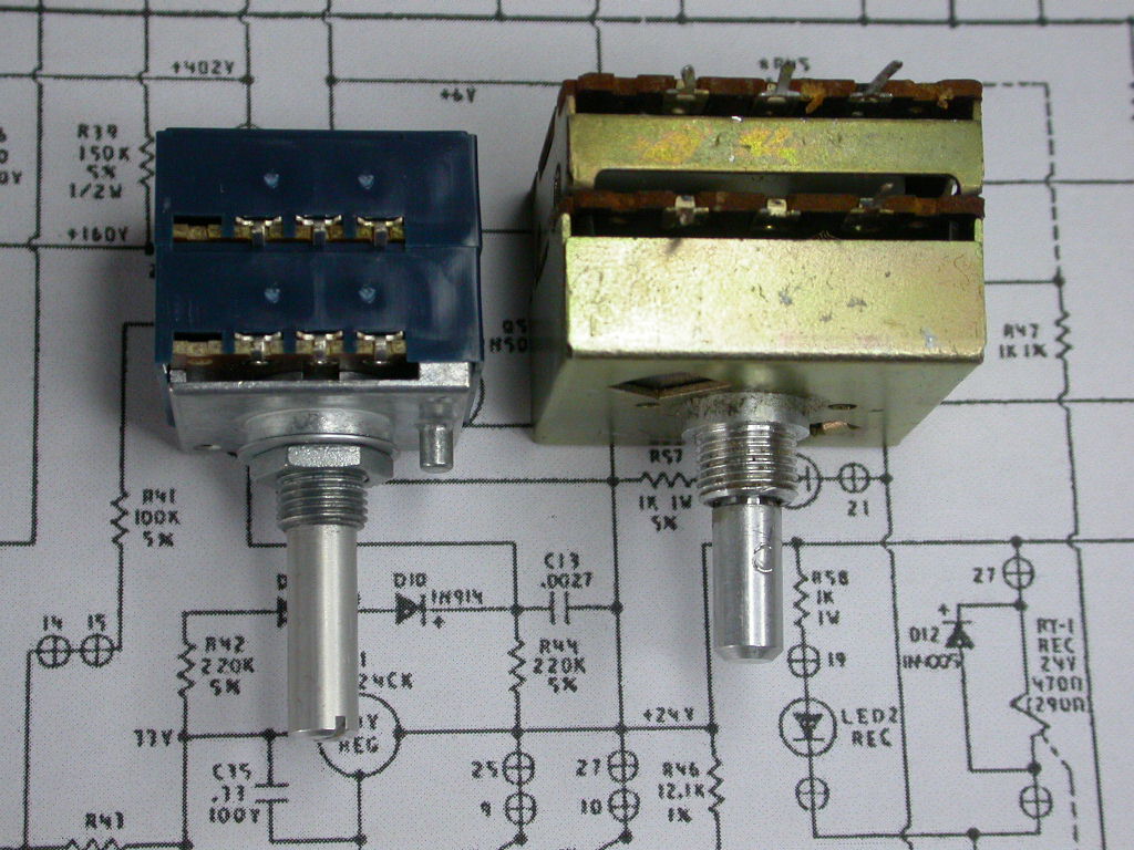
The offending part – the Audio Research SP8 Volume control (right) next to its replacement (left)
You’ll see I managed to snap off the tag from one section of the volume control, though I could have patched it if necessary. It is a 100k log-law (A-law or audio taper) part. ARC run the whole control section at a very high impedance, cascading the 100k linear balance control (presenting a 25k impedance to the volume pot assuming a low source) into the 100k log volume pot, which is then direct-coupled into the grid of V4.
Now you could replace this with a cheesy Chinese 100k log law pot, but bearing in mind you’ve probably got the same problem of being wrapped down at the low end of the travel, you will hate yourself all the time when one channel is louder than the other. So don’t do it. Spring for an ALPS high-end pot. This is your main control interface, you’ll use it every day, and a cheap pot will annoy you every day. I got mine from Tisbury Audio on ebay, look for ALPS Blue Velvet.
I got a 50k version. What’s that all about, I am replacing a 100k pot? Well, this is my chance to lose about 6dB of gain – by putting a 47k film resistor in series with the hot end of the pot I make it as if I have a 100k pot but never get to use the top half, thereby extending the bottom part of the travel which is where everything happens. I make the gain distribution of the SP8 a bit better suited to the modern world (I’ve already got the low-gain mod ARC recommend in Note 2 of the schematic), but without upsetting the circuit conditions. The balance control still feels as if it has a 100k pot after it, and to V4 it feels like there is a timid listener who never gasses the amp up past the halfway mark on the original volume control (OK probably about 10 o’clock due to the log taper).
ARC SP8 preamplifier volume control post-mortem
ARC SP8 preamplifier volume control carbon track after 30 years
It was clearly old age that’s done for this. It was well made, with multiple tracks and multiple fingers covering the track. It might have been possible to clean this one up with switch cleaner, but in the end it’s got a lot of miles on it, and the carbon track just wears. A cheesy touch that honestly I wouldn’t have thought ARC would have done was the volume control has a stepped detent built in. There is no reason for this, indeed I was usually only on the first four detents and sometimes used the halfway positions. It isn’t a stepped attenuator and there’s no need for ARC to make out it is. However, they had to lubricate the detent mechanism; and this may have hastened the pot’s demise, as it was the first wafer that went scratchy. You can see a gunkiness on the slip-ring.
ARCs cheesy faux-stepped attenuator mech. And all that grease, oh my…
Over thirty years, that grease wants to move. It migrated to the shaft of the control, that was sticky and greasy when I removed the knob, and I suspected some of it eventually got onto the track. Even geniuses like ARC have bad days, and introducing a part than needed greasing and stopping me using every part of the volume control was a Bad Idea in my view.
The other trouble is the replacement is smaller, it has a different pin pitch, and the pins are in a different plane to the old one. This isn’t about to sit on the PCB as a drop-in replacement 😉 That’s a blessing in disguise, since there’s enough space to solder in some extensions to the pins and space to lose the 47k series resistors without modding the PCB in any way. Which would feel kinda rude.
First there’s some mechanical argy-bargy to sort. The ALPS pot has a anti-rotation pin. There’s no place for that to go on the SP8 chassis. Simple decision, do I drill the hole in the chassis of the SP8 or do I saw off the pin? I went for the saw off the pin option, funnily enough.
See that pin on the Blue Velvet? It’s gotta a go, because I’m not drilling my SP8. You can also see that the plane of the tags front to back and side to side is different between the old and new
The eagle-eyed will see there’s a great big slot in the Blue Velvet to avoid the tags shorting out on the front metal plate. That is where all the swarf is going to go from sawing the tag, because swarf is like that. So tape over the gap before you saw the pin off, okay. Otherwise you get to replace a scratchy old pot with a scratchy new one.
Sellotape stops the swarf falling into the ALPS Blue Velvet giving me an instant scratchy new volume control
Next up was matching up the 47k series resistors. I want them the same, I don’t care about the exact value. They were nominally 2% but what the hell, it’s easier to check this before soldering them in. They both read 46.8k on my AVO M2007. Good enough for me.
matching the series resistors. The both read this, I won’t bore you with the second picture showing the same reading…
Observing the difference between old and new, I figured some extension wires would take out the slack, since the new control is smaller it would stand a little off the board. Obviously I no longer have the control to locate the left-hand side of the PCB, but I figure three other controls are good enough. So I wire some pins to the volume control and sleeved them. I sacrificed a couple of resistors for their leads which seemed about right for the holes in the Audio Research circuit board.
ALPS replacement SP8 volume control prepared with flying leads
ALPS replacement SP8 volume control prepared with flying leads
Then it’s a case of carefully matching up pins and holes, pre-bending the wires to get the plane of the replacement to roughly match the old one. Don’t solder anything yet, just bend the outer leads over to stop it falling out into the guts of the amp.
ARC SP8 replacement volume control loose in board
ARC SP8 replacement volume control loose in board
Now it’s time to lower the board back into the amp and marry up the switches and pots with the holes. The new volume control has some play because of the unsoldered wires, to take up its rightful position in the front panel. Tighten up all the nuts, using the ½” AF socket for the three old controls and socket for a M9 nut for the ALPS pot. I used a 3/16ths W ring spanner, because it fitted.
Now everything is seated, solder the flying leads of the pot to the board, and wire back the ARC flying leads that go the the line stage input. Be very careful to make sure no bits fall into the amp, or if they do that they are extracted. Remember there is 630V B+ in there, looking to cause some trouble for someone… It was hard to get the camera in behind the installed pot to show it in service but this gives you the general idea
Installed replacement ARC SP8 volume control
Installed replacement ARC SP8 volume control
Now double check everything, then power up the amp. I fed mine to a oscilloscope in parallel with some computer speakers. You don’t want to be down a preamplifier and the rest of your hi-fi if it all went horribly wrong. I fed a CD player into the back, and with some judicious manipulation of the unmarked switch shafts established that I had a working amplifier. On powering down the CD, I rotated the volume control and observed the absence of scratchiness. On the scope I was looking for any bursts of oscillation or general spuriae and bad attitude but there was none at any position of the volume control. I tested all the inputs and switch positions, and they all worked apart from the tape monitor input, where the switch had a low level on one side. I don’t use that so I can live with it, though I stuck a label on the monitor socket to remind myself should I ever want to use it. It would involve demounting the PCB on the switch panel and changing the switch, which I can’t match aesthetically. I’d have to change all the switches for diddy little ones.
It was now down to breaking out the IPA – that’s Isopropyl alchohol, not India Pale Ale, and cleaning some of the accumulated grime of the last 30 years from the recesses. Not the innards – in the end thirty years of thermal cycling means if it ain’t broke or in obvious distress don’t touch it, but it was time to clean my knobs.
A dirty knob or two. Particularly the one on the left, where the grease from the detent of the pot worked its way out along the shaft, through the grub screw on the underside to gunk up the anodised finish
A dirty knob or two. Particularly the one on the left, where the grease from the detent of the pot worked its way out along the shaft, through the grub screw on the underside to gunk up the anodised finish
The IPA worked well, but couldn’t get more than about half of it off, and didn’t get into that groove. However the remarkable power of a cheap ultrasonic cleaning bath with some tepid water and washing-up liquid worked wonders.
Happiness is… an ultrasonically cleaned knob
Time to refit them, starting with the two switches on the right-hand side (which need the larger diameter inside for the slightly thicker shafts).
I didn’t want to change this pot, and indeed I first changed the tubes, in the hope I had a knackered tube. I didn’t, but they were due a change anyway, being over 10 years since I last did this. I got mine from Watford Valves. Overall the total job cost me about £110 for the new valves and pot, and about three hours of time.
The alternative would have been to get something like a Naim Audio NAC 172 XS. Eventually I will have to move away from the Transporter because I have just discovered that Logitech is end-of lifeing the whole Logitech Media server and players, and going to cloud. I am not having my hi-fi depend on anybody’s cloud 😉 Will I still be listening through this when I am 80? Probably not, but hell, hopefully it has a few more years in it yet.
The SP8 – a legacy from days before CD
Thirty years ago there were no CDs, good audio was to be had from vinyl LPs or not at all. It might have been different if Compact cassette hadn’t killed of reel-to-reel, but vinyl was where it was at. The SP8 is a legacy from vinyl days – records chucked out loads of out-of band signals and crud, you needed decent headroom to pass clicks and pops through the RIAA de-emphasis[ref]seems funny to write about the RIAA without cursing them, their lawyers, and the horse they rode in on, but they did a good job in the early days, standardising the frequency equalisation curves for LPs[/ref] without stretching them into dirty great thumps. The downside of the SP8 was it was noisy with low-output MC cartridges, but I used an AT1000T moving-coil transformer ahead of it which sorted that.
The SP8 served me well in my vinyl playing days, and it worked well with digital sources too, with one proviso. The trouble with moving to digital is that line level took a big hike from the old 0.775Vrms[ref]Wikipedia claims domestic gear was lined up at -10dBV which is half that at 0.316 Vrms in which case it’s gone up by 12dB rather than 6. I don’t know if this is US-specific [/ref] to typically 2V p-p with the move to CD. The Naim CD-5XS has a line level of 2.1Vrms and the Transporter runs 2Vrms. And the trouble is the SP8 line stage is high gain – about 26dB, so I was always wound way down on the volume control, it would rarely get to 9 o’clock whereas in vinyl days I’d be happy at 11. This probably contributed to making it scratchy, as the first part of the track on the volume pot gets all the action.
I have tried patching the Transporter straight to the Naim power amp and using the digital volume control but it wasn’t that special. And up-down buttons as the main volume control user interface sucks. Whaddya do when you want to listen out for if it’s your phone or doorbell ringing?
The SP8 doesn’t owe me anything – thirty years of listening pleasure is a decent ROI on its capital cost. However, my hifi system is stable and well matched to itself and to me. Any change risks running into the Diderot effect so it was worth taking a flyer on fixing this.
The surprising repairability of old gear
Vintage gear is surprisingly repairable, because you get to replace component parts. It’s surprising that in three decades of progress people still haven’t come up with a better volume contro lthan the humble potentimeter, and these are still widely available. Whereas I’m not going to be fault-finding to component level on an iPod in thirty years time. or even still using it daily. However, an awful lot of portable audio like that is still repairable, because you most commonly get trouble with jacks, power supplies/batteries and cases. Most of these are to be found on ebay or are standard parts. I’ve serviced mobile phones and the like – case replacements in particular are an easy win, but I’ve replaced keys and joysticks before. However, portable gadgets aren’t going to be serviceable in the far future like this was, and nor are they liekely to be usable in the long term future.
For completeness’ sake, here is the rest fo the SP8 manual and parts list for the Mk1.
I’m a fan of Ciseco’s OpenKontrol Gateway. It doesn’t get anywhere near enough love on their site compared to the flighty Eve. Where it scores is that it’s a cheap way of making stuff happen and I like that.
It makes a dandy data logger, basically get the RTC kit and the SD card socket, slam one of their XRF radios in the left hand socket plus a LLAP thermistor device within 50 yards and you’re all set 🙂 You can add more thermistor devices while the datalogger is running and they get logged too without bumping it. And all for less than about £80 total system cost, what’s not to like? Okay in an ideal world the power consumption could come down a little bit as the OKG is in receive only mode, but it’s livable with – using 8 NiMH AAs gave me a couple of days runtime.
This saved our tail with finding out what the soil temperature was like in and outside a polytunnel earlier this year
What you can also see in the OKG picture is a Wiznet 5200 Ethernet card. What I didn’t realise is that this damn thing has a microcontroller inside. And it’s reset at the same time as the Arduino, so you get some sort of evil who-dares-wins race to get out of the starting blocks when that reset line goes High. The horse you want to win is the Arduino, so as the Wiznet’s ready to get initialised by the Arduino, but it doesn’t seem to happen that way.
Looks like with some configs the wiznet wins the race, and presumably gets confused when it sees data and stuff. I never got it to work reliably with the SD card datalogging. I the got another OKG, this time without the SD card and RTC option, just for posting LLAP devices from the XRF to Cosm. And this damn thing was about 50% reliable, it gave me a world of hurt until I discovered this natty fix for this sucker over at Open EnergyMonitor. I am so grateful to them. Basically you dis the reset on the Wiznet and ground the sonofabitch once the Arduino powers up, so you know where it starts from rather than whatever it got to see on the data lines as everything Arduino and SD card and XRF and what have you fired up. Sounds good to me, and it works. I had considered chucking a monostable at this to ground the line for a sec so the Arduino can sort itself out, but caught the Wiznet getting its knickers in a twist after a while having started okay. So the option to deck it if it returns more than five -ve values for etherclient post is necessary. I went off pin 3 of the RH socket which is arduino pin 6 ISTR, but I need to see if there is a genuinely spare pin because one day I might want to use the OKG as an RF to RF gateway which would mean getting both slots into service. I’m open to pinching the red status LED if necessary 😉
The Wiznet seems actually reliable now, and if it does get itself stuffed in an IoT application returning a negative value for a post five times in a row I simply reset it and reinit the device. It’s not the end of the world if five temperature readings get lost, as long as recovery is possible 😉
I have used two Dallas DS18B20 sensors to log the soil temperature inside and outside a polytunnel, as well as a free-standing RF thermistor probe for the air temperature.
reading of soil and air temp inside and outside polytunnel
The air temperature reading clearly has issues in the day, but the soil temperature readings show the value of a polytunnel. The blue trace, inside, shows the soil temperature to always remain above 5C, which is apparently important for seed germination. The temperature excursions to be smaller, ranging over about 8C rather than 12 for the outside soil temperature, and the outdie soil temperature falls to 0 at one point.
The air temperature suffers in the day from the problem of the greenhouse effect, which is of course the whole point of a polytunnel, but the sensor additionally suffers from not being in thermal balance in the day.
Measuring temperature in a room is easy, and the one-box LLAP sensors do that fine. However, setting them up where the sun shines on them means the sensor gets heated by the sun and no longer accurately reflects the ambient air temperature, because the black case is heated up faster than it radiates / convects heat away, so it’s no longer in thermal equilibrium.
The way to address this is to use an aspirated thermomenter, which has a thermal screen from above to stop solar radiation heating the sensor and a fan to waft air across the sensor – it doesn’t need a high fan speed but it needs some.
However, at night solar radiation isn’t a problem, so the air temperature reading is useful in the night, where it shows the air temperature falling below zero inside the polytunnel from about 9pm to 6am.
The soil sensors are about 5cm below the surface, which is typically where seeds would be planted.
One of the things it would be good to track at the farm is light level over the year. It’s part of a tri-sensor I want to develop to read light level, temperature and humidity, which will then radio-report to an OpenKontrol Gateway to log the values centrally.
The correct tool for this job is apparently a pyranometer which uses a thermopile to sense the heat incoming to a black surface. Presumably the thermopile, being a differential device by design, tracks variations in ambient temperature. About 40% of incoming solar energy is visible light, and a similar amount is infrared.
The obvious cheapest tool for the job is a silicon photocell, which doesn’t respond across the whole spectrum, but mainly to visible light and IR. Unfortunately the IR peak coincides with a water vapour absorption peak that makes it sensitive to water vapour too because the spectral response peak is in the IR. David Brooks’ website summarises the issues there. In his other website, he describes the fact that there’s a case to be made for measuring just the visible spectrum for photosynthetically active radiation. I’m going to start with a regular Si photocell and fight that issue later 😉
So there’s a lot wrong with the approach, but as Brooks notes –
Despite their shortcomings, solar-cell based pyranometers are widely used for meteorological, environmental, and agricultural monitoring, and their performance relative to thermopile-based pyranometers has been studied extensively. Although they are not suitable for producing stable and highly reliable research-quality data required for detecting small long-term changes in insolation, data from simple solar cell pyranometers are still very interesting. They can be used to characterize the potential of sites to produce solar power and to demonstrate seasonal effects on available solar energy. Pyranometer data recorded at intervals of a minute or so provide a record of cloud cover during the day and it has been shown in peer-reviewed scientific literature [Duchon and O’Malley, 1999] that it is possible to use pyranometer data to classify cloud amounts and types even when individual measurements of insolation are not highly accurate. It follows that such data can also be used to track long-term changes in cloud amount and type – an extremely important indicator of climate change.
Looks good enough for me. I’m going to use a BPX65 because I have some and they’re cheap-ish. The BPW21 is a better choice for visible light only, but it’s dearer, I don’t have one and it’s easy enough to switch the photodiode later on.
Right off the bat I don’t like the design of the system described on David Brooks’ page, because it takes the photodiode and rams the signal into a 470 ohm resistor across the diode. In itself there’s nothing wrong with that, but because the resulting signal voltage is low, to keep the response linear, it demands 12-bit resolution from the datalogger A/D converter though it only uses the few lower bits. Making the sensor cheaper makes the datalogger needlessly dearer without using the extra precision you’re paying for, and makes the whole system more sensitive to noise and crap due to the low signal level. However, it makes it simpler to replicate, which probably was the main design brief for that project, but I can do better because I have control of the whole system.
I’m not going to fiddle about with Arduino here – though Arduino makes some things easier it makes things dearer, and seems to lead people to a penchant for digital sensors like the TSL235R or even truly digitised sensors like the DHT22 humidity sensor with proprietary non-standard interfaces. These get hard to service in future years, compared to an analogue voltage interface.
I want a single supply transimpedance amplifier that I can limit to 5V so I don’t nuke the A/D converter of my PIC. Fortunately I have one- a CA3140 can run the input down to 0V or even 0.5V lower, can bring the output to 0V, and the strobe input lets me limit the output to 5V if I run the opamp off a higher voltage (haven’t decided there yet – if I run it off 5V then there’s no problem).
Looks like once a minute is the fastest that it’s worth sampling this and light level doesn’t really change that fast. The photocurrent is rated at 10nA/lux, daylight is about 10,000 lux peak corresponding to a photocurrent of 100µA. Given a maximum output of 4V the transimpedance resistor should be about 4/100 MΩ = 40kΩ. 39k is the closest preferred value to that, but I took 47k. This is the UK, I can probably expect a little bit less peak sunlight than noon in the Sahara. With the slow response time needed I can slug the frequency response with the 220nF capacitor – this gives me a 10 second RC time constant.
Transimpedance amplifier
You can’t suddenly demand Peak Noonday sun, NOW so I will have to field test this for sensitivity. On the bench it works fine, though the peak output with my bench lamp close to the diode is all of about 400mV. However, it’s not bright as the noonday sun there 😉
The CA3140 is a great opamp for this. Being a MOSfet design, it has virtually no input bias current to speak of, compared to the diode dark current (0.1pA as opposed to 1nA dark current). It can run down to -0.5V on the inputs, and to 0.13V on the output low. I could improve the low end by biasing the input (diode cathode and pin3) up 0.6V on a silicon diode and referring the low end of the A/D converter to that, or just sense it with another input and subtract it in software. The input offset voltage of the opamp is the waek point with MOSFET op-amps – 5mV worst case which would get a bipolar opamp binned.
However, it isn’t the worst limitation on the lowest light that can be sensed, that is the 0.13V saturation point, which would correspond to an current of .13/47k = 2.8µA, an illumination of about 280 lux. This probably needs improving, as it’s higher than a dark overcast day. The 5mV offset voltage limit corresponds to about 10㏓, though it has to be added to the various PIC A/D converter offsets which I haven’t developed yet.
This will need fine-tuning later on, but it’s good enough to get me going and ready to tackle the PIC side of things.
This is the sound of the flow inside the well-house at Chalice Well. Two springs rise in this area – the Chalice Well and gardens are home to the chalybeate Red Spring, rising from a deep underground source with little variation in flow or temperature over the years and seasons. Only a few tens of yards away is the White Spring, which rises from theg round closer to the surface. There is a definite tone to the flow – the well-head has a pentagonal chamber underneath it and the resonance of this makes a peaceful steady sound.
From a field recordist’s point of view life is made more difficult by the A361 carrying HGVs down Chilkwell Street, but the wellhead is far enough away and loud enough that this doesn’t impair the recording.